Table Of Contents
Networking Concepts
WAN Technologies
ISDN
ISDN Components
Frame Relay
X.25
CHAP and PAP Authentication
CHAP Authentication
PAP Authentication
Access Lists
Dialer Interfaces and Dialer Profiles
Dialer Interfaces and Dialer Maps
Dialer Pools
Network Address Translation
Dynamic Host Configuration Protocol
Virtual LANs
VLAN Issues
LAN Segmentation
Security
Broadcast Control
Performance
Network Management
Communicating Between VLANs
VLAN Translation
Designing Switched VLANs
Networking Concepts
This appendix describes concepts that can help you in designing your network and in configuring your router in accordance with the examples in this guide.
This appendix contains the following sections:
• WAN Technologies
•CHAP and PAP Authentication
•Access Lists
•Dialer Interfaces and Dialer Profiles
•Network Address Translation
•Dynamic Host Configuration Protocol
•Virtual LANs
WAN Technologies
This section describes some of the WAN connection types that can be used with Cisco 1700 series routers, such as ISDN, Frame Relay, and X.25.
ISDN
ISDN is a set of digital services that is available through your local telephone company. ISDN digitizes information that is sent over the telephone network so that voice, data, text, graphics, music, video, and other material can be sent over existing telephone wire.
ISDN Components
ISDN components include terminals, terminal adapters (TAs), network termination devices, line-termination equipment, and exchange-termination equipment.
ISDN Terminals
There are two type of ISDN terminals:
•Terminal equipment type 1 (TE1) is designed specifically to work with ISDN. TE1s connect to the ISDN network with 4-wire, twisted-pair cable.
•Terminal equipment type 2 (TE2) is non-ISDN equipment (such as data terminal equipment [DTE]) that predates ISDN standards. TE2s connect to the ISDN network with a terminal adapter.
ISDN Network Termination Devices
Two types of ISDN terminal devices can connect your router to the telephone company's conventional 2-wire local loop:
•Network termination type 1 (NT1)—In North America, the NT1 is provided by the customer. In most other parts of the world, the NT1 is part of the network provided by the ISDN service provider. WAN interface cards that do not have an integrated NT1 must have an external NT1 in order to connect to ISDN services. The Cisco 1604 and ISDN BRI U WAN interface cards each have an integrated NT1.
•Network termination type 2 (NT2)—This more complicated device is usually found in digital private branch exchanges (PBXs).
There is also an NT1/2 device available that can perform the functions of both an NT1 and an NT2.
Services
There are two types of ISDN services:
•Basic Rate Interface (BRI)—This service provides two B channels and one D channel. Each B channel operates at 64 kbps and carries user data. The D channel operates at 16 kbps and carries control and signaling information, although in certain circumstances it carries user data. BRI supports framing control and overhead, and the total bit rate is 192 kbps.
•Primary Rate Interface (PRI)—This service provides 23 B channels (which operate at 64 kbps) and 1 D channel (which operates at 64 kbps) in North America and Japan, resulting in a bit rate of 1.544 Mbps. In Europe, Australia, and other parts of the world, PRI provides 30 B channels, 1 D channel, and 1 maintenance/error channel. Each channel is 64 Kbps, for a total bit rate of 2.048 Mbps.
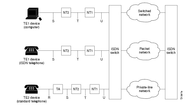
Sample Configuration
Figure 0-1 shows an example of ISDN configuration for various devices used to connect the user to the ISDN network.
Two of the devices shown, the computer and the ISDN telephone, are compatible with ISDN. The third device, the standard telephone, requires a TA to connect to the ISDN network through an NT1 or NT2 device.
Figure 0-1 Sample ISDN Network
Frame Relay
Frame Relay is a method of packet-switching that is used for communication between user devices (such as routers, bridges, and host machines) and network devices (such as switching nodes and modems). User devices are called data terminal equipment (DTE), and network devices are called data circuit-terminating equipment (DCE).
Frame Relay services can be provided by either a public network or a network of privately owned equipment serving a single enterprise.
Frame Relay is a streamlined, efficient, high-performance protocol. It is extremely fast because
•It multiplexes many logical data conversations (or virtual circuits) over one physical link. Multiplexing provides flexible and efficient use of bandwidth.
•It uses fiber media/digital transmission links. These types of physical connections have a high level of data integrity, so Frame Relay does not need to perform error checking. Error checking is time-consuming and can decrease WAN performance.
•It does not need to perform flow control procedures because these types of procedures are done by upper-layer protocols. Frame Relay uses a simple congestion notification mechanism to inform user devices when the network become congested. Congestion notification alerts the higher-layer protocols that flow control is needed.
Current Frame Relay standards support permanent virtual circuits (PVCs) that are configured and managed in a Frame Relay network. The Cisco 1700 router supports switched virtual circuits (SVCs) for DTE interfaces.
Frame Relay also has Local Management Interface (LMI) extensions for supporting large, complex internetworks. Any LMI extension known as common should be implemented in internetworks that support the LMI specification. Other LMI extensions are known as optional.
The LMI extensions are as follows:
•Virtual circuit status messages (common)—Provide communication and synchronization between the network and the user device, periodically report the addition of new PVCs and the deletion of existing PVCs, and provide information about PVC integrity.
•Multicasting (optional)—Allows a sender to transmit a single frame to multiple recipients, supporting the efficient routing of protocol messages and address resolution procedures that typically must be sent to many destinations simultaneously.
•Global addressing (optional)—Gives connection identifiers global rather than local significance, allowing them to be used to identify a specific interface to the Frame Relay network. Global addressing makes the Frame Relay network resemble a LAN, with respect to addressing.
X.25
X.25 is a method of packet switching that is used for communication between user devices (such as routers, bridges, and host machines) and network devices (such as switching nodes and modems). User devices are called data terminal equipment (DTE), and network devices are called data circuit-terminating equipment (DCE).
With X.25, one computer calls another to request a communication session. The called computer can accept or refuse the connection. If the call is accepted, the two computers begin full-duplex information transfer. Either computer can terminate the connection at any time.
User devices communicate with a bidirectional association called a virtual circuit. Devices on a network use virtual circuits to communicate through intermediate nodes without being directly, physically connected to each other. Virtual circuits are permanent or switched (temporary). PVCs are typically used for the most-often-used data transfers, and SVCs are used for sporadic data transfers.
BRI is an ISDN interface consisting of two B channels (B1 and B2) and one D channel. The B channels are used to transfer data, voice, and video. The D channel carries signal and call setup information. IPX, AppleTalk, transparent bridging, Xerox Network Systems (XNS), DECnet, and IP can all be encapsulated as X.25 over the ISDN B channels.
ISDN uses the D channel to carry signal information. ISDN can also use the D channel in a BRI to carry X.25 packets. The D channel has a capacity of 16 kbps; the X.25 over D channel can use up to 9.6 kbps.
You can set the parameters of the X.25-over-D-channel interface without disrupting the original ISDN interface configuration. In a normal ISDN BRI interface, the D and B channels are bundled together and represented as a single interface. The original BRI interface continues to represent the D, B1, and B2 channels.
Because some end-user equipment uses static terminal endpoint identifiers (TEIs) to access this feature, X.25 supports static TEIs. The dialer recognizes the X.25-over-D-channel calls and initiates them on a new interface.
X.25 traffic over the D channel can be used as a primary interface when low-volume, sporadic interactive traffic is the normal mode of operation. Supported traffic includes IP, IPX, AppleTalk, and transparent bridging.
CHAP and PAP Authentication
In configuring your router, you must select a method of authentication. Authentication is used for security and for identifying who is calling in so that the called router can correctly forward packets to the correct interface. This is generally required when dialer rotary groups are used and multiple sites are calling into a single router.
The configuration examples in this guide use Point-to-Point Protocol (PPP) with Challenge Handshake Authentication Protocol (CHAP) or Password Authentication Protocol (PAP) for security and authentication. CHAP and PAP, when used with PPP encapsulation, allow routers to authenticate incoming calls.
CHAP Authentication
With CHAP, a remote device attempting to connect to the local router is requested, or challenged, to respond. When the local router receives the challenge response, it verifies the response by looking up the name of the remote device given in the response. The passwords must be identical on the remote device and the local router. The names and passwords are configured using the username command.
In the following example, Router Macbeth allows Router Macduff to call in using the password "bubble":
username Macduff password bubble
In the following example, Router Macduff allows Router Macbeth to call in using the password "bubble":
username Macbeth password bubble
PAP Authentication
Like CHAP, PAP is an authentication protocol used with PPP. However, PAP is less secure. CHAP passes an encrypted version of the password on the physical link, but PAP passes the password and host name or username in clear text.
When interactive mode (rather than dedicated mode) is used on asynchronous lines, the username command allows a router to verify a username in an internal database before the user can call in to the router. In the following example, user Joe Smith is allowed to call in to the router if he uses the password "freedom":
username JoeSmith password freedom
Access Lists
Access lists control packet filtering on Cisco routers by limiting traffic and restricting network use by certain users or devices. Although there are several purposes for using access lists, the configuration examples in this guide use access lists to control the transmission of packets on a specific interface.
An access list is a sequential collection of "permit" and "deny" conditions that apply to network addresses. Packet addresses are compared to the conditions in all access lists configured in the router. The first match determines whether the packet is accepted or denied by the router. Because the router stops testing conditions after the first match, the order in which the conditions are defined in the access list is critical. If a packet does not match any conditions configured in an access list, the router rejects the packet.
For detailed information on how access lists work and how to configure them, refer to the "Configuring IP Services" chapter in the Network Protocols Configuration Guide, Part 1, publication, which is available on the Documentation CD-ROM that came with your router.
Dialer Interfaces and Dialer Profiles
A dialer interface is a WAN interface on the router that is not continuously connected to a remote device; it dials the remote device whenever a connection is required. Configuring an interface on a Cisco router to dial a specific remote device at specific times requires configuring dialer profiles.
You can use dialer profiles to configure the router's physical interfaces separately from the logical configuration required for a call. You can also configure the router to allow the logical and physical configurations to be dynamically bound together on a per-call basis. All calls going to or from the same destination subnetwork use the same dialer profile.
A dialer profile consists of the following elements:
•A dialer interface (a logical entity) configuration with one or more dial strings, each used to reach a specific destination subnetwork.
•A dialer map class defining all the characteristics for any call to the specified dial string (telephone number).
•An dialer pool of physical interfaces to be used by the dialer interface. The physical interfaces in a dialer pool are ordered according to priority.
Dialer Interfaces and Dialer Maps
A dialer interface configuration is a group of settings the routers uses to connect to a remote network. One dialer interface can use multiple dial strings (telephone numbers). Each dial string is associated with its own dialer map class. The dialer map class defines all the characteristics for any call to the specified dial string. For example, the dialer map class for one destination might specify a 56-kbps ISDN speed, and the map class for a different destination might specify a 64-kbps ISDN speed.
Dialer Pools
Each dialer interface uses one group of physical interfaces, called a dialer pool. The physical interfaces in a dialer pool are ordered based on priority. One physical interface can belong to multiple dialer pools. ISDN BRI interfaces can set a limit on the minimum and maximum number of B channels reserved by any dialer pool. A channel reserved by a dialer pool remains idle until traffic is directed to the pool.
When you use dialer profiles to configure dial-on-demand routing (DDR), the physical interface is configured only for encapsulation and for the dialer pools to which the interface belongs. All other characteristics used for making calls are defined in the dialer map.
Network Address Translation
Network Address Translation (NAT) provides a mechanism for a privately addressed network to access registered networks, such as the Internet, without requiring a registered subnet address. This mechanism eliminates the need for host renumbering and allows the same IP address range to be used in multiple intranets.
NAT is configured on the router at the border of an inside network (a network that uses nonregistered IP addresses) and an outside network (a network that uses a globally unique IP address; in this case, the Internet). NAT translates the inside local addresses (the nonregistered IP addresses assigned to hosts on the inside network) into globally unique IP addresses before sending packets to the outside network.
With NAT, the inside network continues to use its existing private or obsolete addresses. These addresses are converted into legal addresses before packets are forwarded onto the outside network. The translation function is compatible with standard routing; the feature is required only on the router connecting the inside network to the outside domain.
Translations can be static or dynamic. A static address translation establishes a one-to-one mapping between the inside network and the outside domain. Dynamic address translations are defined by describing the local addresses to be translated and the pool of addresses from which to allocate outside addresses. Allocation occurs in numerical order, and multiple pools of contiguous address blocks can be defined.
NAT eliminates the need to readdress all hosts that require external access, saving time and money. It also conserves addresses through application port-level multiplexing. With NAT, internal hosts can share a single registered IP address for all external communications. In this type of configuration, relatively few external addresses are required to support many internal hosts, thus conserving IP addresses.
Because the addressing scheme on the inside network may conflict with registered addresses already assigned within the Internet, NAT can support a separate address pool for overlapping networks and translate the addresses as appropriate.
Dynamic Host Configuration Protocol
Dynamic Host Configuration Protocol (DHCP) is a client-server protocol that enables devices on an IP network (the DHCP clients) to request configuration information from a DHCP server. DHCP allocates network addresses from a central pool on an as-needed basis. DHCP is useful for assigning IP addresses to hosts connected to the network temporarily or for sharing a limited pool of IP addresses among a group of hosts that do not need permanent IP addresses.
DHCP frees you from having to manually assign an IP address to each client.
DHCP configures the router to forward User Datagram Protocol (UDP) broadcasts, including IP address requests, from DHCP clients. DHCP allows for increased automation and fewer network administration problems by
•Eliminating the need for the manual configuration of individual computers, printers, and shared file systems
•Preventing the simultaneous use of the same IP address by two clients
•Allowing configuration from a central site
Virtual LANs
A virtual LAN (VLAN) is a switched network that is logically segmented on an organizational basis, by functions, project teams, or applications, rather than on a physical or geographical basis. For example, all workstations and servers used by a particular workgroup team can be connected to the same VLAN, regardless of their physical connections to the network or the fact that they might be intermingled with other workgroup teams. Reconfiguration of the network can be done by means of software rather than by physically unplugging and moving devices or wires.
A VLAN can be thought of as a broadcast domain that exists within a defined set of switches. A VLAN consists of a number of end systems, either hosts or network equipment (such as bridges and routers), connected by a single bridging domain. The bridging domain is supported on various pieces of network equipment; for example, LAN switches that operate bridging protocols between them, with a separate bridge group for each VLAN.
VLAN Issues
VLANs are created to provide the segmentation services traditionally provided by routers in LAN configurations. VLANs address scalability, security, and network management. Routers in VLAN topologies provide broadcast filtering, security, address summarization, and traffic flow management. None of the switches within the defined group will bridge any frames, not even broadcast frames, between two VLANs. Several key issues need to be considered in designing and building switched LAN internetworks:
•LAN Segmentation
•Security
•Broadcast Control
•Performance
•Network Management
LAN Segmentation
VLANs allow logical network topologies to overlay the physical switched infrastructure in such a way that any arbitrary collection of LAN ports can be combined into an autonomous user group or community of interest. The technology logically segments the network into separate Layer 2 broadcast domains whereby packets are switched between ports designated to be within the same VLAN. By restricting traffic originating on a particular LAN only to other LANs in the same VLAN, switched virtual networks avoid wasting bandwidth, a drawback inherent to traditional bridged and switched networks in which packets are often forwarded to LANs with no need for them. Implementation of VLANs also improves scalability, particularly in LAN environments that support broadcast- or multicast-intensive protocols and applications that flood packets throughout the network.
Security
VLANs also improve security by isolating groups. High-security users can be grouped into a VLAN, possibly on the same physical segment, and no users outside that VLAN can communicate with them.
Broadcast Control
Just as switches isolate collision domains for attached hosts and forward only appropriate traffic out a particular port, VLANs provide complete isolation between VLANs. A VLAN is a bridging domain and all broadcast and multicast traffic is contained within it.
Performance
The logical grouping of users allows an accounting group to make intensive use of a networked accounting system assigned to a VLAN that contains just that accounting group and its servers. That group's work will not affect other users. The VLAN configuration improves general network performance by not slowing down other users sharing the network.
Network Management
The logical grouping of users allows easier network management. It is not necessary to pull cables to move a user from one network to another. Additions, moves, and changes are achieved by configuring a port into the appropriate VLAN.
Communicating Between VLANs
The Cisco 1700 series routers uses the IEEE 802.1Q protocol for routing between VLANs.
The IEEE 802.1Q protocol is used to interconnect multiple switches and routers and for defining VLAN topologies. IEEE 802.1Q support is currently available only for Fast Ethernet interfaces.
Procedures for configuring routing between VLANs with IEEE 802.1Q encapsulation are provided in Chapter 4, "Configuring Routing Among VLANs with IEEE 802.1Q Encapsulation."
VLAN Translation
VLAN translation refers to the ability of the Cisco IOS software to translate between different virtual LANs or between VLAN and non-VLAN encapsulating interfaces at Layer 2. Translation is typically used for selective inter-VLAN switching of non-routable protocols and for extending a single VLAN topology across hybrid switching environments. Translation also allows the bridging of VLANs on the main interface; the VLAN encapsulating header is preserved. Topology changes in one VLAN domain do not affect a different VLAN.
Designing Switched VLANs
By the time you are ready to configure routing between VLANs, you will already have defined them through the switches in your network. Issues related to network design and VLAN definition should be addressed during your network design. Refer to the Cisco Internetworking Design Guide and appropriate switch documentation for information on these topics:
•Sharing resources among VLANs
•Load balancing
•Redundant links
•Addressing
•Segmenting networks with VLANs
Segmenting the network into broadcast groups improves network security. Use router access lists based on station addresses, application types, and protocol types.
•Routers and their role in switched networks
In switched networks, routers perform broadcast management, route processing and distribution, and provide communications among VLANs. Routers provide VLAN access to shared resources and connection to other parts of the network that are either logically segmented by means of the more traditional subnet approach or that require access to remote sites across wide-area links.
")
")
")
")
")
")
")
")
")
")